Industrial RO System Flow Diagram & P&ID | Professional Drawing Guide for Water Plants
Industrial RO system flow diagram/P&ID is standardized schematic drawing and piping & instrumentation drawing that visually marks pipeline layout, equipment arrangement, instrument points, valve positions and control logic for industrial reverse osmosis pure water stations in engineering design, construction and acceptance phases. It is necessary to mark the model, flow rating and installation position of each liquid filter clearly on P&ID drawings, which can effectively lock pretreatment protection parameters and avoid system operation abnormalities caused by mismatched filter specifications during actual commissioning. Engineering designers and construction teams can match physical equipment layout referring to drawing standards of Professional Design of RO System for Industrial Pure Water Stations and acceptance specifications from Industrial RO Equipment Acceptance Criteria for High-standard Water Stationsto realize one-to-one correspondence between drawings and on-site physical devices. Our P&ID drawing service covers process flow drafting, instrument tag marking, safety valve & drainage layout, control signal wiring drawing and annotated operation parameter table. The finished drawings are applicable to small low-flow RO skids and large multi-module centralized industrial pure water systems, widely adopted in pharmaceutical, new energy, food, chemical and power industrial water treatment projects. This article introduces the composition of RO flow diagrams & P&ID drawings, reverse osmosis operating principle, drawing marking technical specifications, drawing production quality control standards, drawing application scenarios in different industries and common drawing design errors, supporting your whole-cycle industrial RO project design, construction acceptance and daily equipment operation management.

1. Product & P&ID Drawing Service
Introduction Industrial RO system flow diagram/P&ID serves as the most fundamental engineering document throughout the whole lifecycle of industrial reverse osmosis water stations, covering preliminary design, factory equipment fabrication, field pipeline installation, system commissioning, routine operation and equipment overhaul. Many small-scale water treatment projects only rely on simple hand-drawn flow sketches rather than formal standardized P&ID drawings, resulting in disordered pipeline laying, misplaced instrument sensors, unreasonable valve setting and difficult later equipment maintenance. A complete standardized P&ID drawing integrates process flow logic and automatic control signal paths, guiding every construction and operation link with unified graphic symbols and marked data parameters.
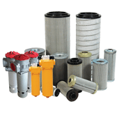
Liquid filter related information marking is an indispensable core content on all RO system P&ID drawings. Drawings must record filter model, design flow, pressure detection points, inlet/outlet valve layout and drain pipeline position. Ambiguous or missing liquid filter marking will lead to wrong model selection during equipment matching, filter overload blockage and subsequent irreversible pollution of expensive RO membrane elements after system operation. Clear liquid filter schematic layout is the basic guarantee for the long-term stable operation of the whole RO water system.
We formulate tiered P&ID drawing compilation standards for different project scales. Small and medium-sized factory single-line pure water skid projects adopt simplified P&ID drawing mode formulated according to the process framework of Professional Design of RO System for Industrial Pure Water Stations, only retaining core process pipelines, necessary instruments and main control valves to reduce drawing reading difficulty for on-site operators. Large industrial park multi-module centralized pure water stations adopt full detailed P&ID drawings, including branch pipeline balance layout, interlock protection signal logic and emergency cut-off valve setting, and all acceptance detection items are marked in accordance with the data index of Industrial RO Equipment Acceptance Criteria for High-standard Water Stations. For pharmaceutical and semiconductor ultra-pure water RO systems, we add sanitary pipeline slope marking, CIP cleaning loop schematic and sterile sampling point layout in P&ID drawings to meet industry regulatory audit requirements.
Many informal P&ID drawings have non-uniform graphic symbols, missing parameter annotations and unclear signal wiring logic, bringing huge hidden dangers to later system debugging. Our standardized industrial RO P&ID drawing output includes 7 core modules: overall process flow diagram drafting, equipment graphic symbol marking, liquid filter & pretreatment assembly parameter annotation, pressure/conductivity/flow instrument tag number coding, pipeline size & material marking, automatic control interlock logic drawing and drawing version update management sheet. Construction personnel install pipelines and equipment strictly according to formal P&ID drawings; the completed RO system can steadily output qualified pure water for workshop cleaning, raw material preparation, boiler makeup water and circulating cooling water supply. Accurate industrial RO system flow diagram and P&ID drawings are essential technical documents for standardized construction and standardized operation of industrial pure water stations.
2. Reverse Osmosis Working Principle & P&ID Drawing Design Logic
Reverse osmosis adopts pressure-driven physical membrane separation mechanism, which is the core theoretical basis for compiling all industrial RO system flow diagrams and P&ID drawings. When external driving pressure is higher than the natural osmotic pressure of raw water, water molecules penetrate polyamide semipermeable RO membranes, while dissolved salts, colloids and suspended pollutants are intercepted on the concentrate side to realize raw water purification. All pipeline paths, equipment arrangement positions, instrument monitoring points and automatic interlock protection programs on P&ID drawings are designed around this mass separation law to maintain the stable hydraulic environment required for normal membrane operation.
The standard four-stage industrial RO operation flow and corresponding P&ID drawing marking modules are as follows:
Stage1: Multi-stage precision pretreatment filtration drawing module
Liquid filter and multimedia filter schematic icons are drawn on the front section of P&ID drawings, with rated flow, pressure difference monitoring points and manual drain valves annotated. This pretreatment drawing module forms the primary protection boundary of the overall process in the scheme of Professional Design of RO System for Industrial Pure Water Stations.
Stage2: Dosing unit and high-pressure pump drawing module
Mark pump model, rated pressure, outlet pressure transmitters and metering dosing tank pipeline layout on P&ID diagrams, set pressure low/high interlock stop signals to prevent membrane damage caused by abnormal pump pressure.
Stage3: RO main membrane separation rack drawing module
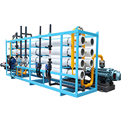
Draw membrane pressure vessels, product water pipelines and concentrated water regulating valves, mark front & rear pressure sampling points to monitor membrane fouling status in real time. Medium and small water systems adopt the modular layout mode from Professional Design of RO System for Industrial Pure Water Stations.
Stage4: Intelligent control & automatic flushing drawing module
Draw PLC signal transmission lines, automatic flushing solenoid valves and remote feedback signal interfaces on P&ID drawings, realizing automatic periodic flushing of membrane components.
For two-stage ultra-pure water RO systems applied in electronic and pharmaceutical industries, independent flow paths and instrument marking areas are divided for primary and secondary RO branches respectively on P&ID drawings.

3. Core Standard Technical Parameters for RO Flow Diagram & P&ID Drawing
We set unified standardized drawing marking parameters for all finished P&ID documents, and all annotations must conform to the following numerical benchmarks:
Pipeline specification marking: Caliber, material and design flow velocity are marked on each pipeline, flow velocity controlled within 1.0~2.0m/s for conventional process pipelines.
Liquid filter drawing parameters: Mark design flow, working pressure grade and pressure difference alarm threshold, ensuring inlet raw water SDI ≤5 in actual operation.
Membrane section marking indexes: Annotate membrane quantity, rated operating pressure and design water recovery rate (60%~78% for single-stage RO).
Instrument marking rules: Each pressure gauge, conductivity meter and flowmeter corresponds to a unique tag number, with upper and lower alarm limit values noted synchronously.
Safety protection marking: High-pressure pipeline safety relief valve set pressure and emergency shutdown interlock conditions are clearly drawn on P&ID drawings.
Drawing reference standard: All acceptance data annotation items refer to the index range specified in Industrial RO Equipment Acceptance Criteria for High-standard Water Stations.
Drawing version management: Record drawing revision number and update time to avoid construction errors caused by expired drawings.
4. Quality Control Standards for Industrial RO P&ID Drawing Production
Formal P&ID drawing preparation implements multi-level drawing review mechanisms to eliminate drawing defects that affect on-site construction effect:
First, raw working condition data verification: All drawing parameter annotations are based on actual raw water quality and on-site layout data provided by customers; liquid filter model and pipeline caliber are matched with real system load to avoid theoretical drawing mismatching actual working conditions.
Second, graphic symbol unification: Strictly follow international water treatment P&ID symbol standards for equipment, valves and instruments to ensure that engineers of all parties can accurately read drawing information.
Third, double review mechanism of drawings: After the initial drawing is completed, the process designer and control engineer conduct two rounds of review respectively to correct drawing omissions and logic errors before formal drawing delivery.
Fourth, supporting document delivery: Deliver matched equipment list, parameter table and drawing operation instructions together with P&ID drawings, remind maintenance personnel to check liquid filter pressure difference data according to drawing marked monitoring points in daily work.
5. Industrial Application Scenarios Supporting RO Flow Diagram & P&ID Drawings
Our standardized P&ID drawing customization service matches the construction demands of various industrial pure water stations:
Pharmaceutical purified water station: P&ID adds CIP cleaning loop drawing and sanitary pipeline marking, complying with GMP factory construction norms.
Semiconductor ultra-pure water production line: Two-stage RO independent P&ID layout, strengthen multi-stage liquid filter monitoring point marking to guarantee ultra-low conductivity effluent.
Food processing factory conventional pure water system: Adopt simplified P&ID drawings designed by Professional Design of RO System for Industrial Pure Water Stations, balancing drawing cost and practicality.
Thermal power plant boiler feed water RO system: Mark anti-scaling dosing pipeline and high-pressure safety protection logic on P&ID drawings for high-hardness raw water characteristics.
General chemical processing factory: Standard P&ID drawings with complete pretreatment and main membrane process marking for daily cleaning water supply.
New energy lithium battery workshop 24h water system: P&ID drawing marks uninterrupted power supply control logic and emergency bypass pipeline to prevent water supply interruption.
Raw water characteristics, factory workshop layout and continuous production hours differ in different regions. Our drawing engineers adjust P&ID detail marking content and pipeline layout mode after analyzing customer field data, matching drawing design content with long-term stable operation requirements of on-site RO equipment.

6 Groups of Standard FAQ
FAQ1 Q: What core drawing content is contained in a complete industrial RO system flow diagram & P&ID drawing?
A: It includes overall process flow layout, liquid filter pretreatment parameter marking, membrane rack pipeline drawing, instrument tag coding, valve and safety component layout, control interlock logic schematic, supported by the process framework of Professional Design of RO System for Industrial Pure Water Stations and acceptance indexes of Industrial RO Equipment Acceptance Criteria for High-standard Water Stations.
FAQ2 Q: Why must liquid filter information be completely marked on RO P&ID drawings?
A: Liquid filter is the first physical barrier for raw water purification. Incomplete drawing marking will lead to incorrect filter model selection and unreasonable monitoring point setting, resulting in filter blockage and membrane pollution faults during equipment actual operation.
FAQ3 Q: What is the difference between a simple flow sketch and formal P&ID drawing?
A: Simple flow diagrams only reflect the approximate equipment connection sequence; standard P&ID drawings contain accurate pipe sizes, instrument parameters, control interlock relations and safety protection settings, which can be directly used for factory processing, field construction and official project acceptance.
FAQ4 Q: Can P&ID drawings be modified arbitrarily after being finalized and delivered?
A: Random revision will cause inconsistency between drawings and physical equipment. All drawing modifications need to record version numbers and issue updated official drawings to each relevant construction and operation department synchronously.
FAQ5 Q: What role do P&ID drawings play in the later maintenance of RO equipment?
A: Operators can quickly locate each liquid filter, monitoring instrument and maintenance bypass according to P&ID marked positions, greatly improving the efficiency of daily inspection, membrane cleaning and equipment overhaul work.
FAQ6 Q: What key information cannot be omitted during P&ID drawing compilation?
A: Liquid filter flow & pressure parameters, membrane operating pressure range, instrument alarm threshold values, safety valve opening pressure and emergency cut-off interlock logic are all mandatory marking content that cannot be omitted.
Other products you want to know about:
Ultrafiltration equipment
Automatic Back-flushing Filter
Precision water filter