Step-by-step Guide to Size Industrial Reverse Osmosis Equipment
How to size industrial reverse osmosis equipmentis a core technical procedure to calculate accurate water output, component specifications and system layout according to actual factory water consumption and raw water quality data for stable long-term RO system operation. It is essential to complete the sizing calculation of matched liquid filter assemblies synchronously during equipment dimensioning work to match actual raw water flow load and guarantee qualified inlet water index for subsequent membrane separation units. Design engineers can adopt standardized calculation data and product parameters from Integrated Reverse Osmosis Unit for Compact and Efficient Water Production and 5 T/H RO Equipment Configuration List for Industrial Water Treatment to finish precise equipment sizing and avoid over-sizing or under-sizing problems. Our complete sizing workflow covers raw water sampling testing, peak water demand statistics, membrane element calculation, pretreatment dimensioning, pump power matching and system recovery rate calibration. This sizing method applies to small compact RO skids and large centralized industrial water treatment stations, widely used in chemical, power, food, pharmaceutical and new energy manufacturing sectors. This article elaborates full sizing procedures, RO separation working principle, core sizing technical indicators, quality control requirements for sized components, industry-based sizing schemes and common sizing mistakes, supporting your precise procurement and customized design of industrial RO water systems.

1. Product & Sizing Service Introduction
How to size industrial reverse osmosis equipment determines the overall operating efficiency, water quality stability, initial investment cost and long-term operating expense of the whole pure water station. Many industrial buyers only select RO equipment according to nominal hourly water yield on product labels without systematic scientific sizing calculation. Under actual working conditions, mismatched equipment size will cause insufficient water supply in peak production hours, low system water recovery rate, excessive pump energy consumption and accelerated membrane fouling. Standard scientific sizing takes real on-site working conditions as the only benchmark rather than fixed standard model parameters.
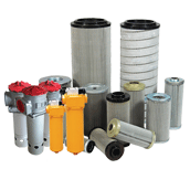
Pretreatment system sizing represented by liquid filter is an indispensable link in the whole RO equipment sizing process. If the liquid filter flow specification is calculated too small, filter cartridges will run under overload and be frequently blocked; oversized filters will cause unnecessary idle investment cost. Reasonable liquid filter sizing stabilizes inlet SDI value fundamentally and protects the service life of expensive RO membrane elements.
We split industrial RO equipment sizing into lightweight sizing for small projects and detailed customized sizing for large water stations. Small and medium factory conventional water demand projects can refer to fixed parameter configurations of Integrated Reverse Osmosis Unit for Compact and Efficient Water Production, quickly finish basic sizing matching according to standard 1T/H,5T/H,10T/H models. For medium flow fixed demand scenarios, designers can refer to the parameter table inside 5 T/H RO Equipment Configuration List for Industrial Water Treatment to complete component matching calculation including pretreatment tanks, membrane quantity and pump power. For large industrial park multi-module water stations, we carry out full customized sizing combined with raw water TDS, seasonal water quality fluctuation and 24h continuous operation load.
Most simple rough sizing only calculates membrane quantity while ignoring supporting pretreatment, pipeline flow velocity and pressure loss calculation, leading to poor actual operating performance after equipment installation. Our standardized industrial RO equipment sizing system contains 7 core links: on-site raw water laboratory testing, daily & peak water consumption statistical calculation, liquid filter & multi-media tank sizing, RO membrane element quantity calculation, high-pressure pump head & flow matching, concentrated water pipeline balance calculation and control system capacity allocation. After accurate sizing and customized configuration, the matched RO equipment can continuously supply stable qualified pure water for workshop component cleaning, raw material blending, boiler feed water and circulating cooling water. Scientific sizing is the prerequisite for cost-effective and stable operation of industrial RO systems.

2. Reverse Osmosis Working Principle & Equipment Sizing Correlation Logic
Industrial reverse osmosis adopts pressure-driven physical membrane separation technology, which is the basic theoretical support for all RO equipment sizing formulas and parameter settings. When the external driving pressure is higher than the natural osmotic pressure of raw water, pure water molecules pass through polyamide semi-permeable membranes, while dissolved salts, colloids and suspended impurities are trapped on the concentrated water side to realize raw water purification. All sizing parameters such as membrane area, pump flow and filter flow are calculated according to the water permeation flux and pollution resistance characteristics of this separation mechanism.
Four-stage standard industrial RO workflow and corresponding independent sizing modules are shown below:
Stage1: Multi-stage precision pretreatment filtration sizing module
Liquid filter and multimedia filter flow capacity are calculated according to maximum raw water inflow. The designed flow margin is generally reserved at 10%~15% to cope with raw water seasonal turbidity rise. This pretreatment sizing is the front guarantee for the normal operation of Integrated Reverse Osmosis Unit for Compact and Efficient Water Production.
Stage2: Dosing system and high-pressure pump sizing module
Calculate pump rated flow and working lift based on membrane required operating pressure + pipeline total pressure loss. Select metering pump flow according to maximum raw water processing volume to ensure uniform addition of anti-scaling agents.
Stage3: Main RO membrane rack sizing module
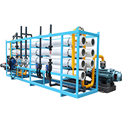
Calculate the total required membrane area by combining target pure water yield and allowable membrane flux value. Small flow scenarios adopt integrated skid configuration from 5 T/H RO Equipment Configuration List for Industrial Water Treatment, while large water stations adopt parallel layout of multiple membrane elements.
Stage4: Intelligent control system capacity sizing module
Match signal acquisition channels, PLC load and power distribution capacity according to the number of sensors, pumps and execution components of the whole system.
For two-stage ultra-pure water RO systems used in electronics and pharmaceutical industries, primary and secondary membrane branches need independent flux calculation and sizing respectively.
3. Core Technical Parameters Used For Industrial RO Equipment Sizing
We formulate unified standard calculation benchmarks for all sizing work, and all configuration parameters must meet the following range requirements:
Design pure water output: Calculate peak hourly water consumption × 1.1~1.2 safety coefficient, standard models cover the specification of 5 T/H RO Equipment Configuration List for Industrial Water Treatment.
Membrane design flux: 10~25 LMH for general industrial water; low flux design for high-pollution raw water to slow membrane fouling speed.
Mandatory pretreatment sizing index: Liquid filter designed flow ≥ actual maximum raw water flow, ensure system inlet SDI ≤5 steadily.
System designed water recovery rate: Conventional single-stage RO 60%~78%, adjusted according to raw water salinity and hardness data.
High-pressure pump sizing index: Rated flow matches total raw water inflow; rated lift overcomes membrane working pressure + pipeline total pressure loss.
Pipeline flow velocity standard: Main pipeline flow velocity controlled at 1.0~2.0m/s to reduce pipeline pressure loss.
Control system load margin: Reserve 20% redundant access capacity for subsequent system upgrading and transformation.
Operating temperature adaptation range: 5℃~40℃, take temperature correction coefficient into membrane sizing calculation.

4. Quality Control Standards In RO Equipment Sizing & Component Selection
Desirable operational performance can only be delivered when precise sizing calculations are paired with premium industrial-grade hardware components:
To begin with, quality benchmarks for pretreatment assemblies. Liquid filters and multimedia tanks sized during the design phase should be built with industrial pressure-proof housings paired with high contaminant retention filter media. Low-cost thin-walled fittings are strongly discouraged, as they are prone to premature failure when operating under continuous design load.
Second, performance standards for RO membrane elements. Specify standard industrial 8040 membrane modules that feature consistent salt rejection performance. Inferior-grade membranes will deliver real-world water output volumes drastically below the theoretical values derived from your sizing formulas.
Third, compliance requirements for pumps and piping assemblies. Deploy horizontal or vertical high-pressure pumps capable of steady pressure delivery. Meanwhile, choose UPVC or stainless steel pipes with rated wall thickness in line with calculated flow velocity values, so as to guard against pipe deformation induced by long-duration pressurized service.
Fourth, internal validation protocol for sizing documents. Every finalized sizing report must undergo a secondary audit by certified water treatment engineers to rectify computational mistakes and parameter mismatches prior to official equipment manufacturing.
Lastly, on-site calibration after equipment delivery and installation. Following fabrication and field erection, technicians should calibrate actual water flow and system pressure metrics, tweaking individual parameters to align with the unique real-world operating conditions at the customer’s facility.
5. Differentiated Industrial Sizing Application Scenarios
Our standardized RO sizing method adapts pure water station construction demands of multiple manufacturing industries:
Pharmaceutical factory purified water station: Low membrane flux sizing + multi-stage high-precision liquid filter design, match sanitary pipeline configuration in sizing parameters.
Thermal power plant boiler feed water RO system: Appropriately improve system recovery rate during sizing, strengthen anti-scaling dosing system matching aiming at high-hardness raw water.
Food & beverage processing plant: Adopt mature sizing parameters of Integrated Reverse Osmosis Unit for Compact and Efficient Water Production, balance investment cost and operational stability.
Chemical industrial water treatment system: Increase liquid filter safety margin during sizing to cope with high organic pollutant raw water environment.
Semiconductor & photovoltaic ultra-pure water workshop: Two-stage graded sizing for primary and secondary RO, strictly control each section’s water flux to guarantee ultra-low conductivity effluent.
General machinery processing factory: Use the finished parameter table of 5 T/H RO Equipment Configuration List for Industrial Water Treatment for fast and economical sizing design.
Raw water quality, production operation mode and water consumption fluctuation are different in various regions. Our engineers adjust sizing safety coefficient and component grade after analyzing customer water sample reports, balancing equipment one-time procurement cost and long-term stable operation performance.
Frequently Asked Questions (6 Groups)
FAQ1
Q: What complete calculation items are included in standard industrial RO equipment sizing?
A: It includes raw water quality testing analysis, peak water demand calculation, liquid filter pretreatment sizing, membrane element area calculation, high-pressure pump parameter matching, pipeline hydraulic calculation, control system load allocation, supported by Integrated Reverse Osmosis Unit for Compact and Efficient Water Production and 5 T/H RO Equipment Configuration List for Industrial Water Treatment.
FAQ2
Q: Why must liquid filter flow capacity be calculated together with main RO equipment sizing?
A: Liquid filter bears the task of raw water impurity interception. Undersized filters will be overloaded and clogged frequently, leading to elevated inlet SDI value and accelerated membrane pollution, shortening the overall service life of RO membrane components.
FAQ3
Q: What problems will be caused by blindly selecting oversized industrial RO equipment?
A: Excessively large membrane area and pump flow will lead to low actual operating load, reduced system water recovery rate, increased idle power consumption and wasted initial procurement capital investment.
FAQ4
Q: Can fixed standard model parameters replace targeted sizing calculation?
A: Standard model parameters such as 5 T/H RO Equipment Configuration List for Industrial Water Treatment are only applicable to conventional normal raw water quality. For special high-salinity, high-turbidity raw water, targeted modified sizing calculation is still required.
FAQ5
Q: What safety coefficient should be reserved during RO equipment sizing calculation?
A: Generally, 1.1~1.2 safety factor is reserved for water yield; 1.1~1.5 margin is reserved for liquid filter and pump flow to cope with seasonal raw water quality changes and production water peak surge.
FAQ6
Q: After completing theoretical sizing calculation, what work needs to be done on site?
A: Complete 72h full-load debugging after equipment installation, calibrate actual water yield, pressure and conductivity data, fine-tune pump operating frequency and dosing dosage according to real on-site operating data.
Other products you want to know about:
Automatic Back-flushing Filter
Ultrafiltration equipment
Precision water filter